4 Bank Marine Battery Charger Wiring Diagram
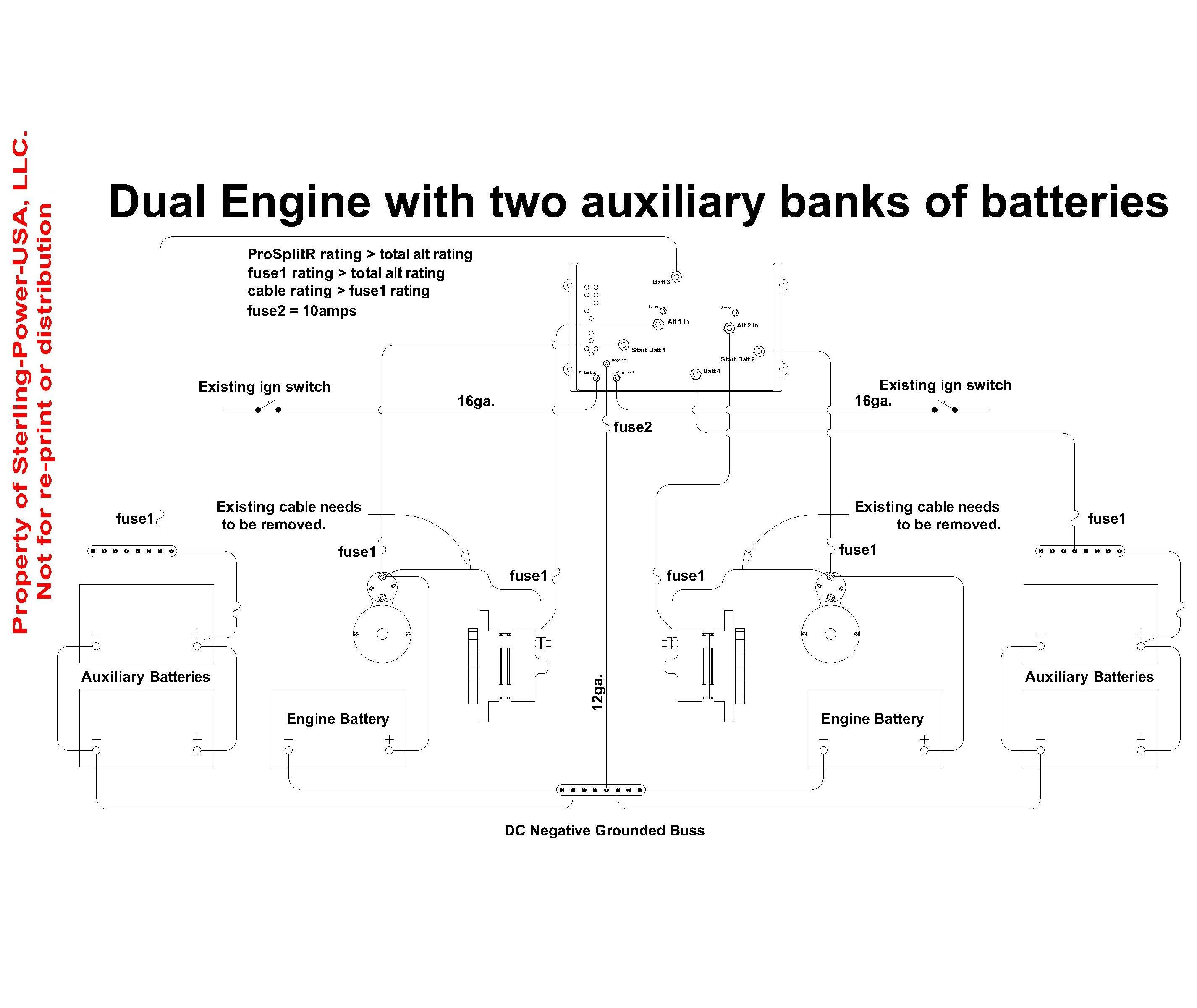
The following basic wiring diagrams display how batteries battery switches and automated charging relays are wired collectively from a easy single battery single engine configuration to a two engine one generator and four battery bank perko dual battery transfer wiring diagram marine diagrams quality. Auto battery charger for 6 or 12 volt sytems.
Marine Battery Chargers Installation Tips & Considerations Community

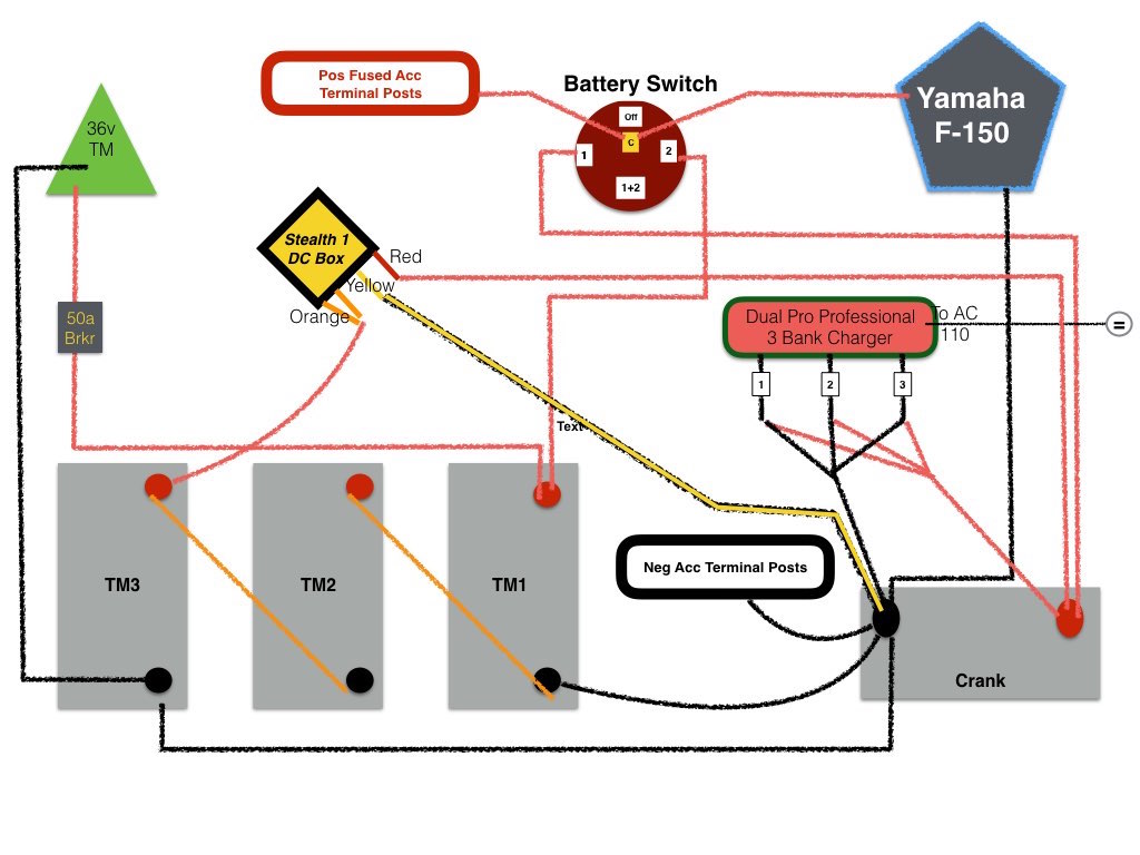
While small and medium trolling motors use a single 12v marine battery, larger trolling motors use larger 24v and 36v systems, and require 2 or 3 marine batteries, accordingly.

4 bank marine battery charger wiring diagram. By facybulka posted on june 7, 2016 29 views. 2 bank battery charger wiring diagram. It gives 12 volt and 5 amps current for quick charging of the battery.
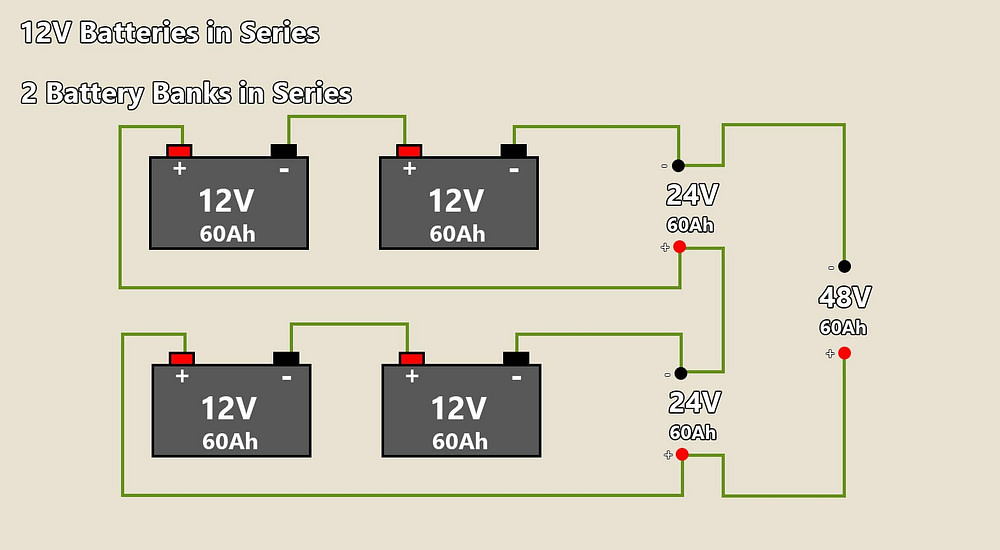
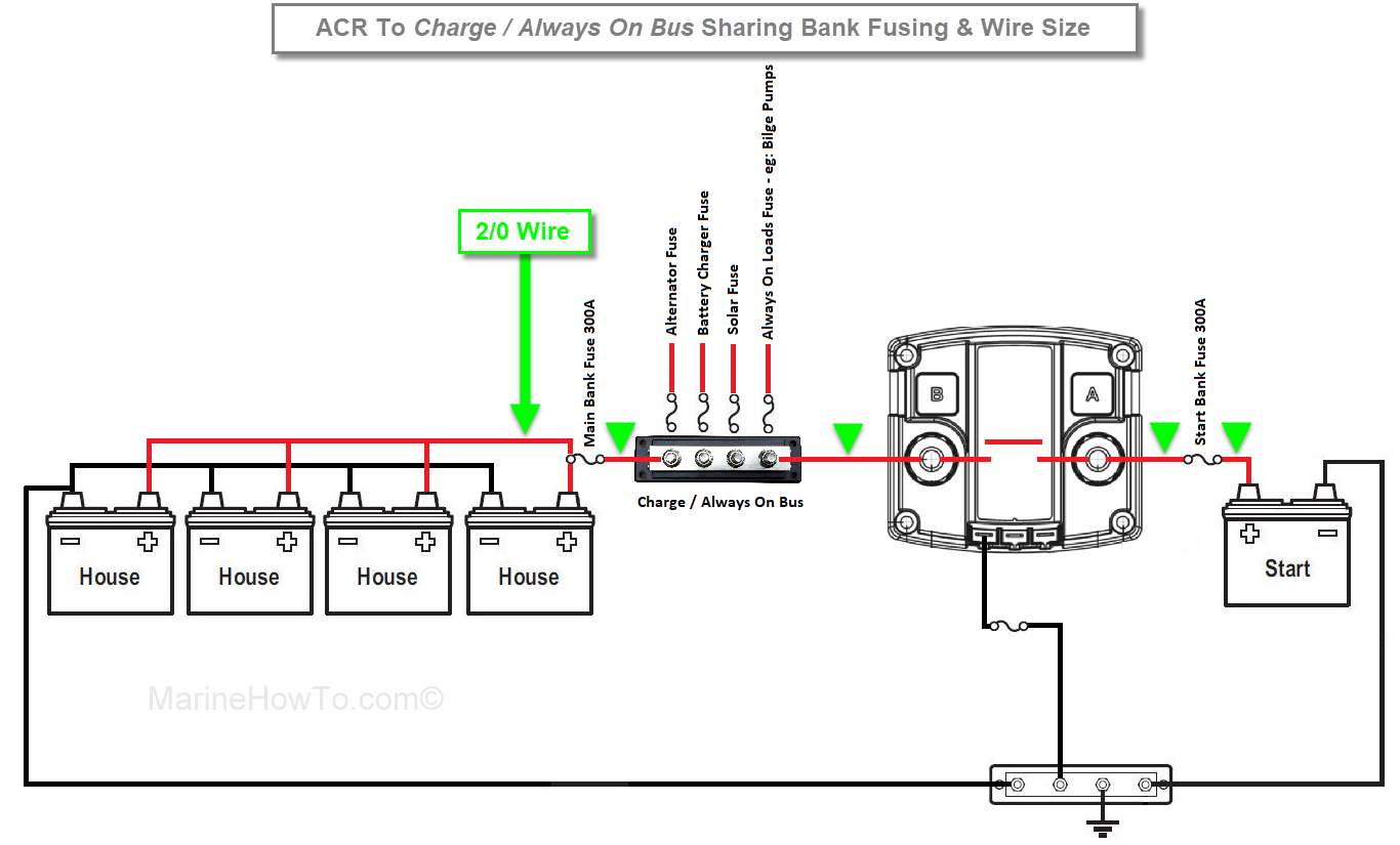
Injunction of two wires is generally indicated by black dot to the intersection of 2 lines. 12 volts to each battery just like if they were 2 individual 12 volt systems. This wire connects back to the pos (+) terminal of the corresponding battery bank to the left.
A 4 bank marine battery charger is designed specifically for the marine environment and should be permanently mounted in your boat and wired directly to your batteries. The charger can be used for 48v, 36v, 24v or 12v systems. Almost all battery chargers out there, for marine use, drop to float before the battery bank has attained 100% soc.
These standards are specific to the marine industry though i think the emergency market such as rescue and ambulance also use ul 1236. Installing 4 batteries need wiring diagram. However, it does not mean connection between the cables.
4.6 out of 5 stars. Add the pair at the helm as a separate battery and now you have 3 big batteries. In an ideal recharge a battery charger would not drop to float voltage until the battery bank had attained the 99.5% to 100% soc point.
Each pair will be wired in parallel. Prosport pfc — universal ac manual. A automobile wiring diagram is a lot like a avenue map, in step with search auto parts.
2 bank battery charger wiring diagram. As stated earlier, the traces in a 2 bank battery charger wiring diagram signifies wires. These “extra” red and black wires are what wire the banks together in parallel, allowing the system to increase the amp hour capacity.
So think of your 4 batteries as 2 big batteries. 3 way switch wiring diagram. These larger motors and multiple batteries are wired in a series pattern, and optimally, the circuit breaker should be wired within 4 of.
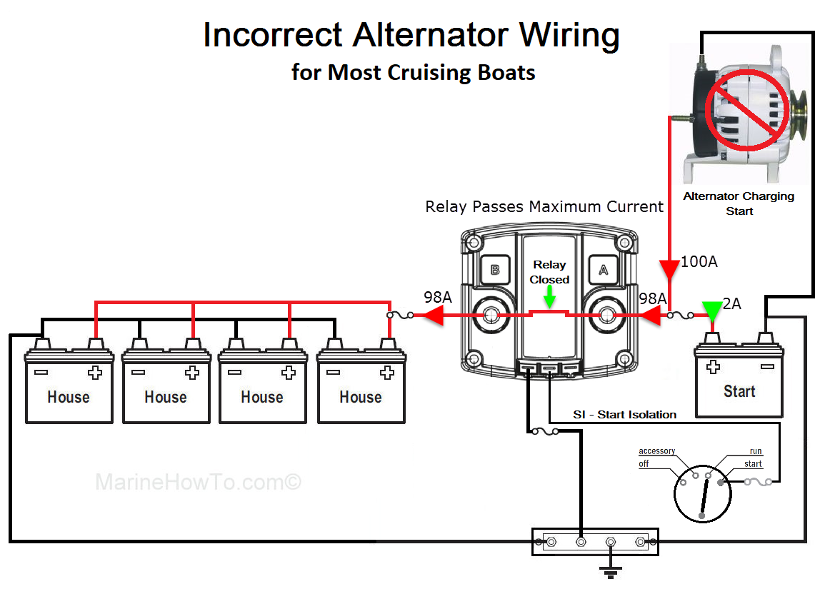
For more detailed wiring guidelines please consult a qualified marine electrician or one of the many. One bank as the starting battery and the other bank as the trolling motor. Sometimes, the cables will cross.
The white neutral wire is splice to each outlet so they share the return path. Each pair is really a single battery in 2 parts; The charger must be grounded to the ac system ground for personnel safety.
The following basic wiring diagrams show how batteries, battery switches, and automatic charging relays are wired together from a simple single battery / single engine configuration to a two engine, one generator, and four battery bank system. It's waterproof, shock and vibration resistant rugged design can be mounted directly onto a variety of applications, including a boat, trolling motor or generator, as well as, a full. In this diagram two outlets are wired in the same box with a separate 120 volt source feeding each.
It can be used for 2 or 3 bank charging system as well by doubling up on different banks. 36 volt battery wiring diagram wiring diagram library. This difference in current between the closest and furthest batteries from your charger can be very significant often up to.
2 bank battery charger wiring diagram. To start with, you can think or your 4 batteries as 2 pair of batteries. 4.8 out of 5 stars.
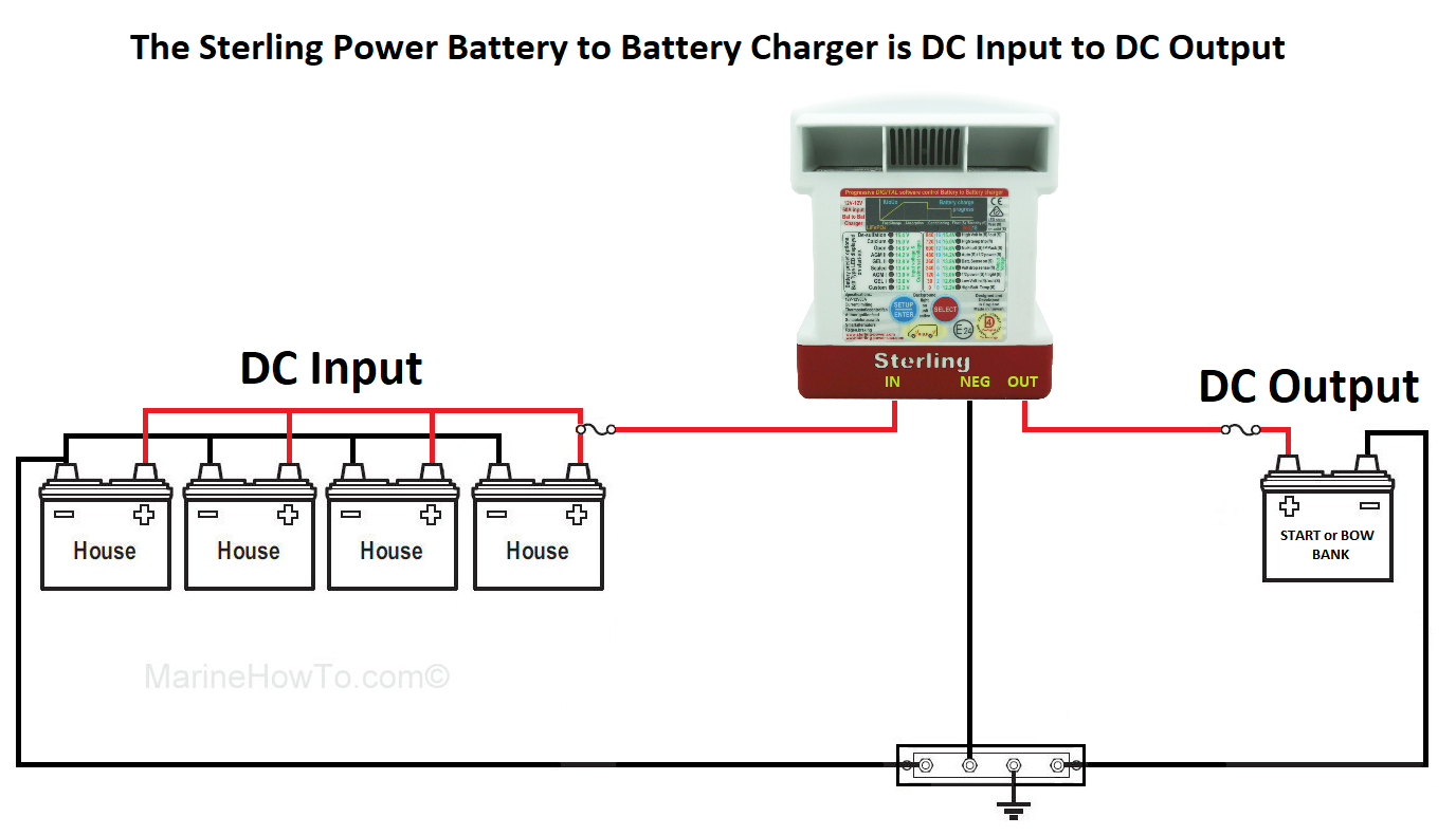
This charger can also be used to charge lead acid or agm batteries. Marine battery wiring and installation + onboard battery charger & fuze/breaker. 2 to 3 times faster than traditional battery chargers.
4 bank marine battery charger for a precise charge. There’ll be primary lines that are represented by l1, l2, l3, and so on. 24 and volt wiring diagrams trolling motor wiring diagrams while small and medium trolling motors use a single 12v marine battery, larger trolling motors use larger 24v and 36v systems, and require 2 or 3 marine batteries, accordingly.
Similarly, the right battery bank has an extra red wire on the pos (+) terminal of the upper right battery. 4 bank marine battery charger wiring diagram 12 volt circuit pdf. Illuminated toggle switch with er yellow id 3219 2 95.
Noco Wiring Diagram Wiring Diagram

Learn to Easily Wire 12V/24V Battery Bank in Parallel or Series DIY Boating Marine Maintenance
24 Volt Battery Wiring Diagram — UNTPIKAPPS

Battery Wiring Diagram / Diagram Ups Battery Backup Wiring Diagram Full Version Hd Quality

I guess it's time to come out of the closet!Bartender 24 Page 61

Noco Wiring Diagram Wiring Diagram
Wiring Manual PDF 12 Volt Battery Wiring Diagram House

3 Battery Boat Wiring Diagram General Wiring Diagram
Our Catalina C34 Upgrades

Marine Battery Charger Wiring Diagram Wiring Diagram
Charge 4 batteries with a 2 bank charger? The Hull Truth Boating and Fishing Forum

4 Bank Marine Battery Charger Wiring Diagram Wiring Diagram Schemas
Boat Battery Charger Wiring Diagram storescenarios
3 Bank Marine Battery Charger Wiring Diagram Wiring Diagram Schemas

Minn Kota Trolling Motor Wiring Diagram Battery schematic and wiring diagram

dual battery charger isolator with switch Google Search Marine batteries, Blue sea, 4ga

3 Bank Marine Battery Charger Wiring Diagram Drivenheisenberg
3 Bank Marine Battery Charger Wiring Diagram Wiring Diagram and Schematic
Wiring Diagrams & Literature for Pro Charge Ultra Marine Battery Chargers, DC powered battery