Wiring Diagram Motor 1 Phase
The above diagram is a complete method of single phase motor wiring with circuit breaker and contactor. It is intended to help all the typical user in building a correct program.
Single Phase Motor Wiring Diagram With Capacitor Wiring Diagram
Residential power is usually in the form of 110 to 120 volts or 220 to 240 volts.

Wiring diagram motor 1 phase. These instructions will probably be easy to comprehend and implement. L1 and l2 are designated as the two connection points representing the two electricity flow path inherent with single phase circuits where a single phase supply voltage is fed to the motors internal circuit. Wire motor wiring diagram circuit diagram maker, wiring diagrams standard motors fantech com au, how to wire a baldor 3 phase motor 13 steps with pictures, single phase motor wiring diagrams gem state electric, terminal markings and internal wiring diagrams rses org, 6 wire 3 phase motor wiring best free wiring diagram, 3 phase 2 sd 12 wire.
The first component is symbol that indicate electrical element in the circuit. 220v single phase motor wiring diagram wiring diagram is a simplified good enough pictorial representation of an electrical circuitit shows the components of the circuit as simplified shapes and the capability and signal associates in the middle of the devices. The 3 phase dol starter wiring diagram is shown below.
And one wiring is called controlling wiring. Ac80, ac90, ac100 single phase motors. For specific leeson motor connections go to their website and input the leeson catalog # in the review box, you will find connection data, dimensions, name plate data, etc.
There are two things which are going to be present in any single phase motor wiring diagram with capacitor. Wiring diagram 230v single phase motor. It represents the physical elements of the electric circuit as geometric shapes, with the real power and connection connections in between them as thin sides.
Diagram dd6 diagram dd7 m 1~ ln e diagram dd8 ln e l1 l2 l3 s/c z1 u2 z2 u1 cap. The other thing that you will get a circuit diagram would be traces. Firstly the stator winding is connected in star an.
The diagram below shows the wiring for a single phase motor and the path through the contactor and overload: Single phase baldor motor capacitor wiring diagram february 17, 2022 by masuzi reverse baldor single phase ac motor single phase motor wiring connection baldor motor capacitor wiring the if a single phase motor hums but Wiring a motor for 230 volts is the same as wiring for 220 or 240 volts.
A circuit is usually composed by many components. In this video, jamie shows you how to read a wiring diagram and the basics of hooking up an electric air compressor motor. Single phase submersible pump starter wiring diagram on water control panel inside to submersible pump submersible well pump sump pump.
Terminal markings and internal wiring diagrams single phase and polyphase motors meeting nema standards see fig. 4 wire reversible psc motor with a triple pole double throw switch. Each component ought to be placed and connected with other parts in particular way.
1) 2.2kw motor with a flc of 5 amps @ 415volts. The basic diagram (view a) shows a circle with two leads labeled t1 and t2. These tips can be used on most ele.
Electric motor wire marking & connections. Wiring diagram also offers beneficial recommendations for assignments which may need some extra tools. Baldor motor wiring diagram single phase wiring diagram is a simplified within acceptable limits pictorial representation of an electrical circuit it shows the components of the circuit as simplified shapes and the knack and signal connections in the company of the devices.
It is extremely easy to draw a wiring diagram; In the above one phase motor wiring i first connect a 2 pole circuit breaker and after that i connect the supply to motor starter and then i do cont actor coil wiring with normally close push button switch and normally open push button switch and in last i do. Single phase motor wiring diagram with capacitor start capacitor run.
15 franklin electric 1 2 hp motor wiring diagram. Wiring diagram will come with numerous easy to follow wiring diagram directions. For most shore facility applications, this is the case.
Diagram dd6 diagram dd8 m 1~ ln e diagram dd9 m 1~ ln e white brown blue l1 l2 n s/c bridge l1 and l2 if speed controller (s/c) is not required diagram dd7 ln e l1 l2 n s/c z2 u2 z1 u1 cap.
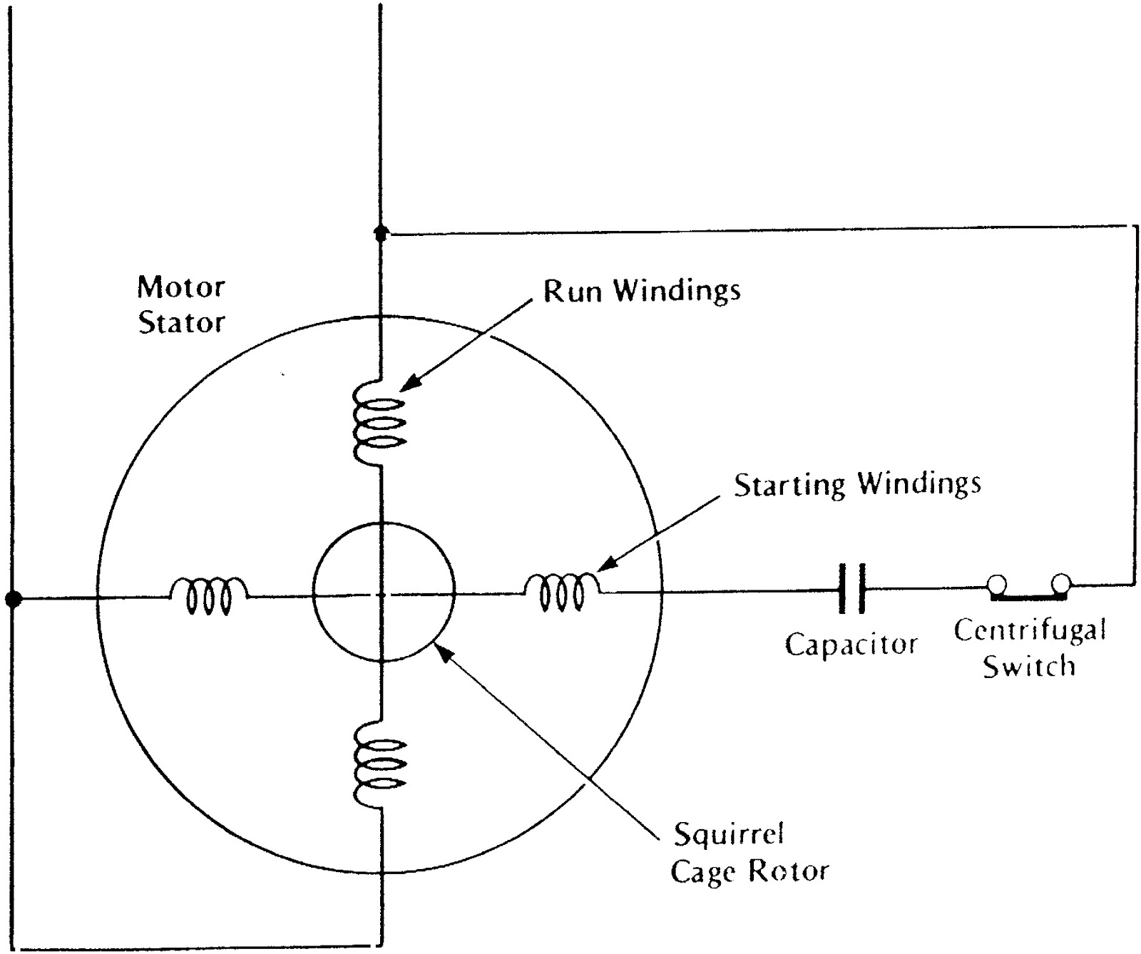
SinglePhase Induction Motor Working Electrical Academia
Single Phase Motor Contactor Wiring Diagram Elec Eng World Electricity, Electrical

wiring How to wire up a singlephase electric blower motor Electrical Engineering Stack Exchange

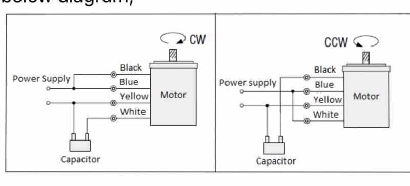
Single Phase Motor Forward Reverse Wiring Diagram Pdf Database Wiring Diagram Sample

Single Phase Motor Wiring Diagram Forward Reverse Database Wiring Diagram Sample

Single phase motor forward and reverse wiring YouTube

1 Phase Motor Starter Wiring Diagram Free Wiring Diagram

Single Phase Motor Wiring Diagram With Capacitor Start Wiring Diagram
Single phase Motor Wiring And Controlling Using Circuit Breaker Electrical Tutorials in Hindi/Urdu

Forward / Reverse Switching of SinglePhase Motor Electric motors & generators engineering
What is the wiring of a singlephase motor? Quora
Wiring Diagram Single Phase Motor Contactor Wiring Forums

Single Phase Motor Wiring Diagram With Capacitor Wiring Diagram
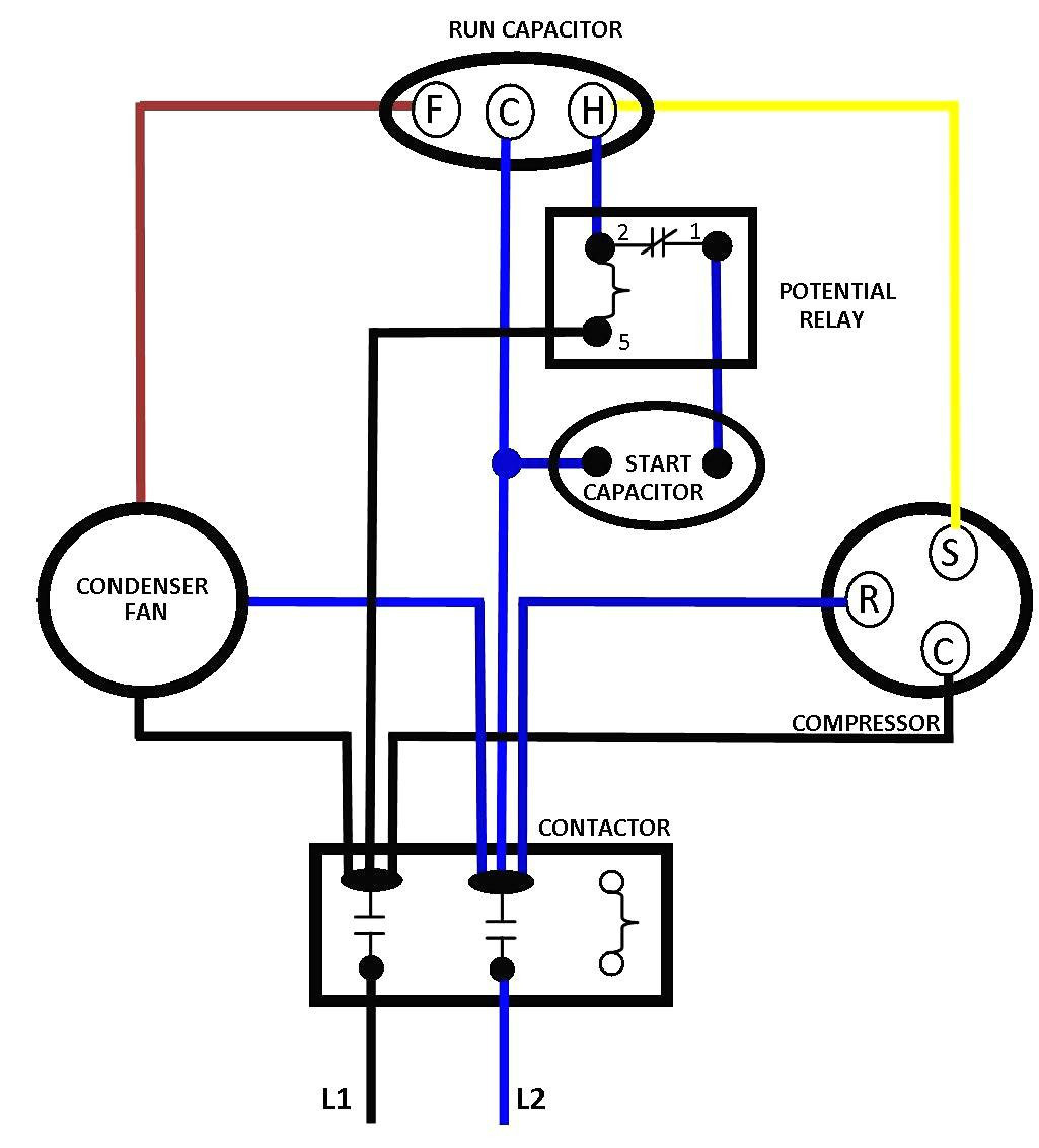
Single Phase Motor Wiring Diagram With Capacitor Start — UNTPIKAPPS

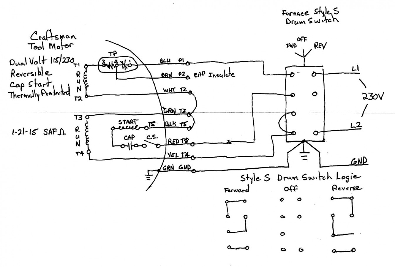
Skyey Motor Wiring Diagram On The Drum Switch Forward And Reverse 1 Phase

I have a Leeson 1 hp single phase reversible motor with wires P1, P2, T2 T3 T8, T4 T5. It is

What is the wiring of a singlephase motor? Quora
Leeson Electric Motor reversing on Drum switch

Types of Single Phase Induction Motors Single Phase Induction Motor Wiring Diagram